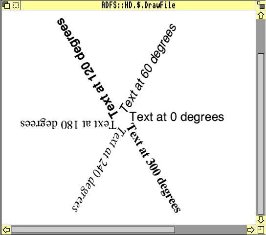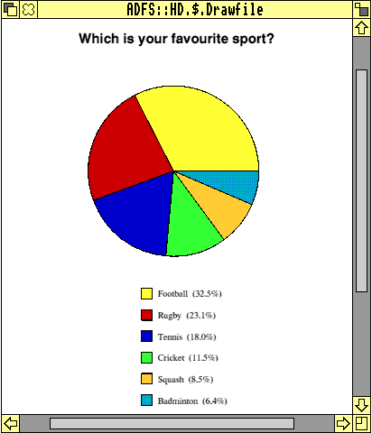
DrawGen Basic is an easy way to create drawfiles from simple Basic programs. In the previous articles, I described how to use simple commands to create geometric figures, how to create paths, including Bezier curves, and how to print text.
Some people have had difficulty getting DrawGen Basic to work. This is because the !DrawGen application (Owen.DrawGen.!DrawGen) on the 12.11 monthly disc won't work as it is. To get it to work, follow this procedure:
Problems were also caused because there are two directories called Programs. The one referred to in article 2 is Owen.Programs. The other contains all the programs from Jim Lesurf's website: Owen.DrawGen.DGBasLib.Programs . The second folder contains the programs in the first directory, but they have been numbered differently. The !ReadMe and dgenTXT files and the Examples directory are to do with !DrawGen, and not DrawGen Basic.
I'm sorry for this confusion. I have asked Paul to include the complete !DrawGen, which includes the above changes, on this month's disc, together with the Programs referred to below (called Programs3).
These 32-bit numbers are used as the parameters of PROCLineColour, PROCFillColour and PROCFontColour.
To make the task of choosing a colour easier, several have been defined as names ending in %, e.g. red%, grey%, lightblue%, etc. They can also be called as Colour%(n%), where n% is a number from 0 to 13, i.e. PROCLineColour(blue%) is the same as PROCLineColour(Colour%(3)).
The list of colours is as follows:
black% or Colour%(0)
red% or Colour%(1)
green% or Colour%(2)
blue% or Colour%(3)
grey% or Colour%(4)
lightgrey% or Colour%(5)
darkgrey% or Colour%(6)
lightblue% or Colour%(7)
darkblue% or Colour%(8)
yellow% or Colour%(9)
magenta% or Colour%(10)
orange% or Colour%(11)
cream% or Colour%(12)
white% or Colour%(13)
These 14 colours are the only ones which can be used with PROCFontColour.
More colours have been defined to be used with PROCLineColour and PROCFillColour. The first three are the pure secondary colours; pureyellow% and puremagenta% are slightly different to the yellow% and magenta% defined above. When the 'pure' colours are printed on paper, they are solid blocks of colour. (The ordinary yellow% and magenta% have spots of black in them.) The pure secondary colours are:
pureyellow% or Colour%(14)
purecyan% or Colour%(15)
puremagenta% or Colour%(16)

The next group defined are the colours used in the draw style menu options Line colour and Fill colour. These are referred to as DrawColour%(n%), where n%=0 to 15. Some of these colours are the same as some of the colours in the first list, but are added here, so that the user can use just DrawColours if required.
e.g. DrawColour%(11) is Red,
DrawColour%(12) is Cream, etc.
PROCLineColour(Draw-Colour%(11)) would therefore give red lines.
See Prog21 for an example of using Colour%(n%) and DrawColour%(n%) as parameters of PROCFillColour. (If some of these different colours appear to be very similar on your monitor, it may be that you are in a 16 colour mode, such as mode 27. The colours are seen more accurately in 256 colour modes, such as mode 28. One advantage of only using the DrawColours, is that the colours are the same in 16 colour and 256 colour modes.)

There is, of course, no reason why users cannot define their own series of colours in their own array, in the order they wish, e.g.
MyColour%(1)=black%
MyColour%(2)=green%
MyColour%(3)=orange%
MyColour%(4)=red%
etc, then use these as parameters, e.g.
FOR n%=1 TO 4
PROCLineColour(MyColour%(n%))
PROCLine(5,n%,10,n%)
NEXT
This can be extended even further using FNNewColour which, as the name suggests, can be used to define a brand new colour. The parameters of this function are three numbers which define the intensity of red, green and blue in the new colour. These numbers have a minimum value of zero, and a maximum value of 255, e.g. paleskin%=FNNewColour(255,189,164) defines a new colour called paleskin%.
This can then be used e.g. in PROCFillColour(paleskin%).
This has 255 parts of red, 189 parts of green and 164 parts blue. See Prog22 for some new colours defined in this way.
See Prog23 where the colour new% is continuously redefined, and mimics the Draw command Grade.
Prog24 also redefines the colour new% to draw a series of circles in an 'interesting' pattern!! (A 256 colour mode is essential to view the drawfiles produced by these programs.)
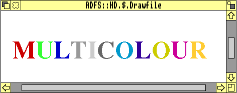
Look at Prog25. This prints a string of letters in a series of colours, by changing the colour with PROCFontColour before printing each letter, but each letter has a different width, so it would be very difficult to calculate where the next letter should be printed. In the program, however, this is easily done for the second and succeeding letters by using the variable Global_End_Print as the x-coordinate of the next letter.
Global_End_Print can be used after you have printed anything with PROCLeftPrint, PROCRightPrint, PROCCentrePrint or PROCFractionPrint. It calculates the width of the string just printed, and gives the x-coordinate to be used for the next string. Notice that the y-coordinate for every letter is the same.
Look at Prog26. This prints out the fonts declared in !DrawGen's !Run file, left-justified, right-justified and centred. Note that Global_Num_Fonts% is the total number of fonts available.
The first drawfile is created as described above, i.e. using PROCStart("Drawfile1"), some commands to describe the contents, and then PROCFinish.
The second (and any subsequent drawfile) is created with the command PROCStartAnother("Drawfile2") instead of PROCStart. After the commands which describe the drawfile, PROCFinish is still used to end the creation of the subsequent drawfiles. (You must"PROCFinish"one drawfile before you can "PROCStartAnother"drawfile!) Note that PROCStartAnother restores the original conditions exactly as they were after PROCStart, i.e. the default units are in force (OS-units), the default line colour is black, the default fill colour is none%, etc.
It is important therefore to redefine everything as was done in creating the first drawfile. In Prog27, for instance,
PROCUnits("cm"),
PROCFont(1,14,14),
PROCLineWidth(0.5,"mm")
are all used both in Drawfile1 and Drawfile2.
Of course, if you want the second drawfile to use a different font, you are free to change the parameters of the PROCFont command. You must not assume that just because the units have been chosen in creating Drawfile1, the same units will still be selected when creating Drawfile2 - they won't be!
Prog27 creates two drawfiles (Drawfile1 and Drawfile2) with rectangles which are slightly different in size. Notice that although the commands to create the two drawfiles are completely separate, the parameters x,y,l,h,px,py are variables in the program, and are carried through the creation of both drawfiles.
Prog28 uses a loop to create three drawfiles, again imaginatively named Drawfile1, Drawfile2 and Drawfile3. Note that in creating the first drawfile (when n%=1) PROCStart is called, whereas for Drawfiles 2 and 3 (when n%>1) PROCStartAnother is called. In this case, the font, line colour and text is changed, as well as the size of the rectangle.
As far as I am aware, you can create as many drawfiles as you like in this way (up to the limit of the number of files in a directory).
In version 1.0 of DrawGen Basic, the drawfile was created in the same directory as the !DrawGen application. In version 1.2, the user can choose where the drawfile will be created.
If the parameter of PROCStart is a simple filename of 10 characters or less, the result will be exactly the same as in version 1.0, i.e. the drawfile will be created in the same folder as the !DrawGen application. All the programs written for version 1.0 will still work in the same way. This applies to PROCStartAnother too.
However, if the parameter of PROCStart is a full filename (in practice, if it includes a "."character), that full filename will be used to create the drawfile.
E.g. take the following program segment:
filename$="ADFS::HD.$.Testfiles.Drawtest"
PROCStart(filename$)
The drawfile will be called Drawtest, and it will be in the directory called Testfiles in the root directory of the hard disc, i.e. the location of the !DrawGen application is ignored in this case.
(Remember that you must have double-clicked on the !DrawGen application first, or none of the programs will work. Perhaps the best way is to include installation of the !DrawGen application in your !Boot sequence.)


Version 1.2 will be added as soon as possible but, it can be found on the Archive website.
Jim Lesurf kindly referred to these articles in a posting to Archive-on-Line. In reply, someone mentioned DrawBasic by Joe Taylor, which is a comprehensive script language to produce drawfiles. Some readers may remember it being described in a series of articles in Archimedes World in 1994, and appearing on the cover disc. I was probably one of the first to register and buy the book at that time, and continued to use it off and on until I came across DrawGen.
DrawBasic is an excellent (and very professionally produced) product, and is now available on the internet, together with a comprehensive tutorial in HTML format. It uses special symbols in its script files, and the programs have their own filetype. However, I prefer using DrawGen Basic because I'm more at home with ordinary procedures and functions. Others might prefer the DrawBasic way of doing things. If you have internet access, try out DrawBasic yourself by downloading it from http://www3.mistral.co.uk/joe_taylor/drawbasic/.
| Source: | Archive Magazine 13.1 |
| Publication: | Archive Magazine |
| Contributor: | Brynmor Owen |